Monolithic Flash Drive Recovery – A Basic How To
Ever wondered what goes into solving a monolithic data recovery case? Here is a brief explanation of what we do to recover data from monolithic flash drives.
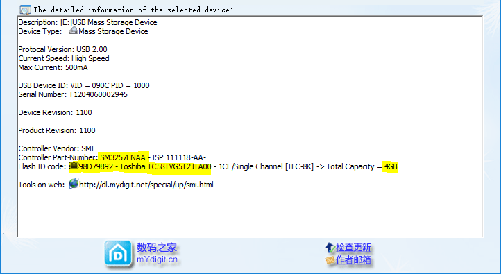
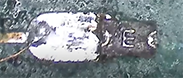
Depending on the manufacturer (eg: NOT SanDisk) you may be able to use ChipGenius to get the ID of the NAND chip. If you can there is a good chance the media is still recoverable and it’s just metadata corruption. In this case, the ID is 98 D7 98 92 this number is helpful in the end as it will let us find the proper order for the data bus.
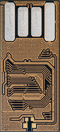
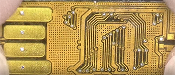
We have developed a special “better” technique for removing solder mask but other companies have been known for using chemicals, fiberglass pens or sandpaper. Either way, the goal is the same to get access to the tiny wires under the circuit board. Those tiny wires connect to the NAND memory chip inside the monolithic chip. By gaining access to the memory chip we can read the data within.
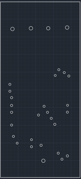
We’re going to connect wires to the via’s. Now that we know where the via’s are we’re going to mask out the rest of the circuit board to protect it when we solder. Most companies won’t even try to solder fine pitches like this unless there are contact points or they’re cover the entire surface in solder and use flux to prevent shorts (not likely). We do this by creating an overlay in CAD that accurate to +/-0.01mm
 .
.
I can’t stress how important this is, always use a resettable fuse on the +5v rail. If there is any kind of soldering short or short inside the monolithic chip this will prevent the drive from frying. You can get them off any SanDisk USB 2.0 flash drive. Once the short is gone they reset and everything works again.
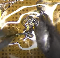 Monolithic soldering is some of the most difficult soldering you’ll ever do in your life. The pitches are tight and unforgiving, a little too much force and you’ll rip the pad right off the PCB. You need thin magnet wire, we use 40AWG and 45AWG depending on the need. You need a semi-powerful microscope, micro-soldering tools, oh and eat something before you solder, you’ll need stable hands for this part.
Diode testing is great if you want to quickly find shorts to ground or disconnected wires. Diode testing is also highly subjective for the use of locating signal wires, “generally” D0-D7 will have the same value, ALE, CLE, WE, RE will have the same value and R/B will have a way off value, however, like I said, highly subjective. Remember red goes on ground.
Nothing sucks more than hunting down duplicate signals or just in general “WTF” signals, checking for continuity saves a lot of time by eliminating duplicate signals from our data acquisitions.
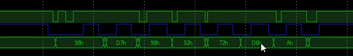
This is an art as if the rest of this wasn’t, sometimes you get lucky like with this drive (I didn’t have the pinout so I’m actually making one in this video) and the signals are obvious, sometimes it’s an utter nightmare. That can take an hour, hours, or days and might require a donor drive. Basically, we’re trying to match squiggly lines with other squiggly to create a known value. Easy right?
Remember that NAND ID, that we found earlier. Now we use it to find the order of the data bus and here it is 98 D7 98 92.